Introduction
The ĹFaraday Paradoxĺ has been the subject of endless curiosity and experimentation
since it was first identified by Michael Faraday in the 1820ĺs. He observed that when a
bar magnet with a field which is symmetrical with respect to the magnet geometry, is
spun about its axis of symmetry, no emf is induced in any conductor which is stationary
with respect to the magnet.
If however the magnet itself is conductive, (and most magnets are), then if it is spun about its axis of symmetry, a radial emf is induced in it, which can be measured between brush contacts at the centre and the periphery of the magnet.
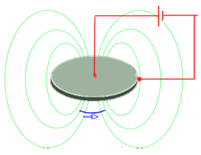 Radial current in magnet between brushes causes it to rotate |
Those who claim this is a 'paradox' argue that since there is no change in either the magnitude or direction of the field through the measurement circuit loop, or the area of that loop, then there should be no emf induced in it. There has been much written about this paradox and papers attempting to explain it continue to appear in the literature. The solutions offered range from a need to modify the basic laws of electromagnetism, to acceptance of the notion that when a magnet spins, its magnetic field does indeed rotate with it [Reference 1]. The basic configuration described above which produces an emf between the centre and edge of a rotating disc magnet, is reciprocal. When a potential is applied to the same terminals, a radial current flows and the conducting segment experiences a Lorenz force normal to both the current flow and the field, which causes it to impress a rotational torque. DC generators and the reciprocal motors based on this principle are variously referred to as ĹFaradayĺ or ĹHomopolarĺ devices.
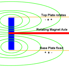
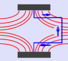
In explaining the paradox, this author points to the operation of the most venerable of all electrical measurement instruments, the moving coil galvanometer. The principle is shown in the diagram at left. A coil is mounted between the poles of a magnet in such a way that its axis of rotation is at the centre of a radial field generated by shaping the poles pieces of the magnet as circular segments, with a central cylindrical core of soft iron. The field between the poles and the core is radial for a limited angular range. The coil is free to rotate about its axis of symmetry with a spring providing a torque which opposes the rotation. When a current passes throught the coil it rotates due to the torque imposed by the interacton of the current and the radial field. When the spring torque is equal to the magnetic torque, the coil comes to rest. As it rotates, there is no change in the magnitude and direction of the field (always radial), or the area of the coil.
If the coil were to be rotated manually, then an emf would be induced in it, despite the fact that there would be no change in either the magnitude and direction of the field, or the area of the measurement loop, which in this case is the coil. As far as the author is aware, there has never been any suggestion that this constitutes a paradox.
The confusion arises due to the three distinctly independent effects involved in the induction process. These are:
An emf is induced in a conductor moving through a static uniform field, but any attempt to measure it would involve connecting a voltmeter to the ends of the conductor, thereby completing a measurement loop in the same field. If the entire loop were to be moved through the field, the voltmeter would not show any emf, because the emfs in each incremental element around the loop would all cancel out. In mathematical parlance the emf 'e' for each element of the loop is equal to the vector product of field magnitude, conductor velocity and direction of motion, for that element. In this case they would add up to zero around the entire loop. This vector product taken around a closed loop is known as the Curl(e) for the loop. If Curl(e)= Zero for a closed loop, it means that there is no resultant emf and therefore no current in the loop.
Suppose now that a conductor is placed on fixed conductive rails connected to a voltmeter, neither of which move with respect to a static uniform field. If the conductor moves along the rails through the field, then the emf induced in it will be recorded by the voltmeter, transmitted to it by the connecting rails. In this case the area of the measurement loop (formed by the rails and the conductor) will have changed as the conductor moves. Alternatively, if the conductor is not moved, but the magnitude of the field changes, then an emf will be induced and recorded by the voltmeter while the change is in progress
Herein lies the root of the confusion. The only way that an emf can be generated without a change in either the magnitude or direction of the field, or the area of the measurement loop, is if part of that measurement loop is physically rotating in the field. That would be a unique situation and one that is indeed the case for the spinning magnet and the moving coil galvanometer. Nevertheless it does conform to the established laws of electromagnetic induction.
In recent years a large amount of literature has appeared on the Internet, along with animations and movie clips of simple experiments involving homopolar motors. The ready availability of the powerful Neodymium-Boron permanent magnets has enabled some very simple and ingenious configurations to demonstrate how a magnet can be made to rotate by applying a current between brushes located at the centre and periphery of a disc magnet. In some cases the only components used are rechargeable AA batteries, a single neodymium magnet suspended by the point of a screw and a length of solid copper wire. Many of these are designed by high school physics teachers for class demonstrations because of the rather dramatic results that they produce.
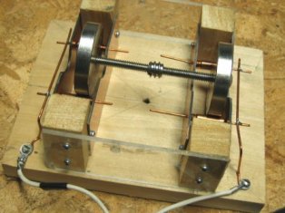
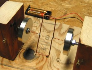
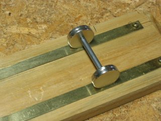 The author constructed a primitive 'rail-gun' arrangement as a demonstration piece. The photo at left shows two pairs of 1" diameter Neodymium magnets attached one pair at each end of a conductive coupling shaft, in such a way that like poles were facing. When placed on brass rails connected to a power supply, a current flows out along one rail, through the two magnets and their coupling shaft, and back via the second rail.
The radial current through each magnet experiences a Lorenz force causing it to rotate. The field directions of each magnet are such the rotational forces generated in each one are in the same sense and the whole assembly accelerates along the brass rails, as can be seen from the accompanying video clip
A number of US patents have been issued for various configurations of Faraday homopolar generators and motors over the years. One of them was issued to Nicolas Tesla himself in the late 1800ĺs. There has been continuing commercial interest in them because of their basic simplicity and the very large currents which can be generated with them. The great drawback is of course the requirement for brush contacts. One of the potential commercial applications is for marine propulsion motors for large vessels, which seems surprising.
It is not always clear when experimenting with homopolar motor/generator configurations, if a given arrangement will work or not. The ultimate criterion is that unless an emf can be generated with a configuration by external mechanical movement, (the dynamo effect), it will not operate as a motor when current is applied via the same terminals. If this were not so, there would be no back emf generated to limit the motor speed, which would violate the law of conservation of energy among others!
It is not necessary for the magnet to move in order to generate an emf. It can be accomplished by having a conductive loop containing a millivoltmeter of some sort, with both leads in contact with any two points on the circumference of the disc. One of them is a fixed contact, the other one is moved around the circumference. The emf is then generated in the magnet along the path between the two contacts. The magnitude is a function of the length of that path and the sweep rate produced by the moving contact.
One way is to fix the magnet on a conducting rail connected to one lead of the millivoltmeter, with the other lead connected to a conductive 'beam' which is see-sawed back and forth across the top of the magnet, as seen in this animation. (the connecting leads are not shown). The red lines at each beam position show the current path, which changes in length and direction as the beam articulates.
Another other way is to allow the magnet to roll back and forth along the fixed rail, with the other contact attached to a point on the circumference which rolls with the magnet, which of course amounts to inverted arrangement of the animation. It is demonstrated in this video clip . In this case the fixed contact point is the alligator clip attached to the rim of a magnet, and the other is the rail along which the magnet can roll.
A simple DC amplifier was assembled on a prototype board using a National Semiconductor JFET dual operational amplifier IC. The two-stage design had the first stage configured as a differential input with a gain of 33, feeding the second stage in a single input configuration, also with a gain of 33, for an overall gain of 1000. A check with a nine volt battery with a 100k/100ohm resistor attenuator confirmed that the gain was indeed 1000 The amplifier was remarkably stable and enabled induced emfĺs of 200 microvolts to be detected unambiguously. A digital Fluke ĹScopemeterĺ was used for making the measurements and its ability to generate, store and display a single sweep signal, including a pre-trigger delay period, was invaluable.
Measurement of magnet flux densities
There are many standard ways to do this, but the easiest and most satisfactory method
under the circumstances was to wind a rectangular loop of wire (with dimensions twice or
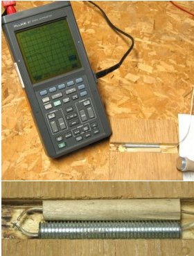
three times the diameter of the magnets), in the form of a figure eight, on pegs in a wooden block with one edge of the loop coincident with one edge of the block. A second identical block secured the loop in a
sandwich. The point of the figure-eight configuration was to reject 60 Hz pickup which it did very effectively. The arrangement is shown in the photo at left.
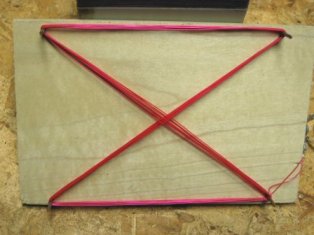 Induction coil for magnetic flux density measurment The figure-eight winding eliminates 60 Hz pickup |
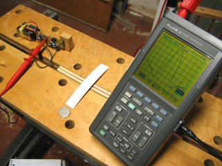 Plastic "runway is used to whip magnet across coil by hand One-chip DC amplifier at left provides gain of 1000 |
With the scope set to single-sweep, the magnet was moved smartly across the edge of the two-block sandwich where the coil was flush using a thin plastic 'runway' to allow a smooth passage.
The waveform resulting from the circular magnet crossing a straight line wire approximates one half of a full sine wave. It has negative lobes at each side, where the wire encounters the field reversals as the magnet approaches and recedes from the wire, as shown in the 'scope trace at right. The area of the negative lobes will always be equal to the area of the positive lobe, thus meeting the condition that Curl(e)=Zero.
Both the time between the zero-crossings and the maximum amplitude in millivolts, could be read with an error of less than 5% . From this the velocity could be calculated knowing the diameter of the magnet, which in turn enabled the flux density to be calculated. The measurements were made on a single 1" diameter magnet and on a stack of three. The mean values of several measurements were respectively 770 and 1900 Gauss
Some idea of the emf's generated by the rail-gun arrangement was obtained by connecting the rails to the input of the DC amplifier and connecting its output to a standard analogue voltmeter, and then rolling the magnet assembly along the rails by hand. The traditional voltmeter effectively filtered the signal to provide only low frequency changes and was therefore far superior to an oscillscope for viewing. The millivolt level signal was easily observed as this video clip clearly shows
|
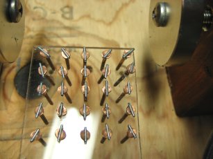
When power is applied, a current flows via one set of rollers and radially through one magnet to the axle, from there it returns via the second magnet and its set of rollers. Despite every attempt to reduce rolling friction, no movement was observed with pulses of 20 Amps from a battery source. A calculation of the torque that would be produced in each magnet, indicated that it would be the equivalent of a weight of 5 grams suspended by a thread attached to the circumference of each magnet. This is based on the formula that a conductor of length l carrying a current I Amps in a flux density T Teslas, experiences a force of N Newtons, (1 Newton is approximately 0.1 Kg). It was clear that this was not nearly enough to cause the assembly to move even enough to detect visible motion.
The necessary dynamo effect was verfied by manually rotating the assembly with the power input leads connected to the DC amplifier with a gain of one-thousand with voltmeter as output, as seen in this video clip
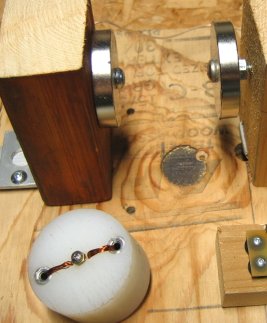
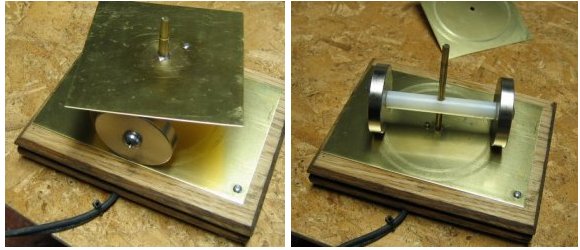 Top-plate electrically connects magnets to centre post |
The current flow is from the post to the rotating top plate (via the sleeve), and then via the magnets (in parallel) to the base plate. The magnets were assembled with like poles facing. It was thought initially that the torque would be generated by the diametral current through each magnet, because the magnets were moving and the instantaneous centre of rotation would be the contact with the base-plate. This would maximise the torque because the Lorenz force would be exerted over a complete diameter, rather than a radius. An experiment was done to check this theory by using a strip of metal to roll one of the magnets along a fixed rail and connecting the strip and the rail to the amplifier/voltmeter detection system. No emf was observed, but when the device was assembled with only one magnet and the top plate was spun by hand, a solid signal was in fact recorded as this video clip shows.
This apparent contradiction was solved when it was realised that the induced emf that was observed, was the result of the flux from the rolling magnet cutting both the top-plate and the base-plate as it circled around the centre post. The radial emf which was generated in the magnet itself between the centre and the circumference, was effectively cancelled out, because both the top and base plates contact points were on the cicumference. The induced emf's in the two plates had opposite polarites causing them to sum in series, because their relative motions were effectively in opposite directions (even though one of them was fixed).
 Plates cut entire cross-section of flux |
The addition of the second magnet does nothing more than make the device mechanically balanced. The emf's from both magnets are effectively in parallel. Once again, the friction was too great to see any movement when 20 Amp current pulses were applied, but the design shows some promise as a homopolar generator capable of extracting the maximum possible emf, by exploiting a complete cross-section of the flux emanating from the magnets.
 Radial field between magnets |
 No emf produced by spinning the wire |
 Curl(e) is zero for this loop when rotated |
In other words The fact that a loop rotating through a radially symmetrical field produces no emf, can be attributed to the fact that the flux density is inversely proportional to the radius, exactly compensating for the increasing tangential velocity of the vertical loop as the radius of the loop is increased. The other interpretation is that since there is no change in either the magnitude or direction of the flux intersected by the loop as it rotates, there will be no net emf induced in it.
 Armature with differential shielding |
 Flux concentrates at ends of shield |
It seems that although there can be no flux inside the shield, it is concentrated at each end and produces the same emf in the conductor being shielded as would be produced without it. It would require a shield of 'infinite' length to prevent this phenomenon. This is yet another example of an immutable corollary of the laws of electromagnetic induction!
The Centeslans have no hang-ups about spinning discs. One of their party pieces is the demonstration involving two adjacent metal horizontal discs, each a metre in diameter spinning in opposite directions, with their spindles electrically connected and their edges separated by a horizontal distance of several centimetres. When they spin at 6000 rpm, the voltage between the disc edges hits more than 30,000 volts, causing a continuous discharge from one to the other. The discharge current through the ionised air is itself subject to a Lorenz force which causes it to travel in a helical path rather than a straight line.
There are no metal filing cabinets on Centesla. It would take for ever to open a drawer because of the huge Lorenz force created by the changing area of the conductive rectangle as the drawer opened. If the resistance of that loop were even one tenth of an ohm, and the width of the drawer only half meter, the voltage generated at a speed of 10 cm/s would be 5 volts, resulting in a loop current of 50 Amps. This in turn would require a force of 2500 Newtons or about 250 Kg. to open it. All metal sheets in warehouses are stacked vertically because if they are stacked horizontally, it is difficult if not impossible to slide one onto or off the stack.
There are multiple transportation problems on Centesla. For example it would simply not be possible to operate conventional metal railways unless there were to be only one vehicle on the tracks at a time. One flatbed or whatever moving along the rails is not a problem, thanks to the truth of the motto statement. If however there is another one parked in some other location on the track, no matter how far away, then it becomes impossible for the first one to move at more than a crawl owing to the Lorenz force generated by the enormous circulating current in the circuit comprising the rails and the two flatbed cars. If the two cars move in the same direction and at the same speed, then the problem disappears, because the area of the loop moving through the one hundred Tesla field does not change in area.
Railway vehicles with rubber tyres are the obvious answer. However, if electric traction is used, the power loop has to be vertical, an overhead wire and a third rail being the only option. The danger with this configuration is that the magnetic moment due to the huge vertical field interacting with the field formed by the power loop, would act to tip the vehicle over.
Air transport is similarly limited. Aircraft wings must be electrically isolated from the fuselage and speeds are limited to prevent dangerous transverse voltages being generated across the fuselage. Airships are used extensively for freight.
One of the two main problems for the luckless inhabitants of Centesla is the interaction of water with the one hundred Tesla field. The salt sea water, with a resistivity of about 0.2 ohm-metres, is highly conductive and any vortices generate huge eddy currents. The result is that the oceans on Centesla take on the consistency of molasses, making marine transport impossible using any conventional craft. Only hovercraft are viable.
The distribution of tap water, with a typical resistivity of 100 ohm-metres, cannot be made via copper pipes. Water flowing through a system of copper pipes will have emfĺs induced which will be normal to the direction of flow. They will generate circumferential currents in the copper pipes which will retard the water flow. All pipes must therefore be made of non-conductive material.
Power distribution via conventional wiring is possible provided that the spacings between conductors in a cable are minimal. Conventional incandescent light bulbs have to be manufactured with straight filaments with fixtures that ensure that the filaments are always vertical. If a light bulb is inadvertently installed with the filament horizontal, it will self-destruct instantly when the power is applied, because the Lorenz force will cause it to vibrate back and forth at the AC power frequency.
Care has to be taken when installing any wiring involving a single conductor in a loop, for example Christmas lights on a tree, because of the interaction of the loop with the Centesla field.
If an irregular non-planar wire loop is connected to a battery, the field generated by the loop will instantly tilt the loop to align the vector resultant of that field with the Centesla field. This might mean flipping the loop over, or a less drastic re-alignment, depending on the attitude of the loop with respect to the Centesla field, and the direction of the current in the loop. Because the Centesla field is uniform, there will be no net translational force on the wire loop once the alignment has taken place.
The Lorenz force however will always act to maximise the area of the wire loop, forcing it into a circle with its plane normal to the Centesla field vector, from whatever geometry (planar or otherwise), the loop originally had.
Swimming is possible in uncontaminated fresh water lakes ľ but definitely not in the ocean. Centesla is subject to global warming, not because of greenhouse gases, but because of the deadly efficiency with which wind energy over the oceans is converted directly to heat, by moving the water and thereby generating electrical eddy currents.
The one advantage which Centesla has is electrical power generation. The AC generators have coils wound on plastic formers, no field coils are necessary ľ just spin them and plug in.
One of the scientific educational kits available is called ĹThe Invisible Tow-barĺ. It consists of a set of metal rails and three model streetcars, all having metal wheels and axles. The wheels have no motive power. The streetcars are placed on the rails at intervals of several centimetres. The resistance of the two loops so created are typically one tenth of an ohm. The configuration is equivalent to a DC linear induction motor. When any one of the streetcars is moved along the rails, an emf is generated which causes loop currents to flow via the remaining ones. The directions of these current are such as to make them move in the same direction as the one being pushed or pulled. As a result, back-emfĺs are induced in both streetcars which act to oppose the loop currents. The net result is that all three move in lock step, as long as there is no friction or ohmic resistance. If work is being done due to those causes, then there will be relative movement between the streetcar being pushed or pulled and the other two. The rails are typically ten centimetres apart, so that moving one of the streetcars at a speed of say 20 cm/s generates an emf of two volts as it cuts the one hundred Tesla field. With one of the other two streetcars restrained, a loop current of 20 A is generated in the 0.1 ohm circuit, which in the one hundred Tesla field creates an opposing Lorenz force of 200 Newtons, or about 20 Kg.
An interesting configuration involves connecting a low value resistor between the rails at their mid-point, thereby allowing a single streetcar to complete a loop circuit. The force required to move the streetcar can be made quite low, depending on the value of the resistor. It is connected in such a way that the streetcar can ride over it without impediment. As the streetcar is pushed toward the resistor, the Lorenz force opposes the movement with a loop current for example in a clockwise direction as viewed from the top. After crossing the resistor, the resistive force is still in the same sense, but the loop current is now in a counter-clockwise direction, although the current still flows through the streetcar and the resistor in the same sense as previously. The direction of the current through the rails however is reversed. This is analogous to the lateral inversion of an image in a mirror.
References: There are many more examples to be found by entering ĹHomopolar motorsĺ or ĹFaraday Motorsĺin a Google search.
1) This Irish EE paper concludes that a NS magnetic field does indeed rotate about its axis of symmetry and that this explains the paradox. They refer to the Tilley experiment of 1915, showing that when a measurement circuit with two loops, one containing a permanent magnet, is switched from one loop to the other, there is a huge change of flux, but no emf is induced. This is really no surprise, merely opening and closing a switch, does absolutely nothing to alter the static flux which is already established!
2) R. Hoadley website
This is very comprehensive and gives layouts at high school level for demos. It also
includes basic theory and animations showing fields produced by different arrays and
shapes of magnets.
3) Scientific toys website
This has animated demos of the rail gun and the various rotating homopolar motors. All
are made of simple components and use batteries
4) Answers.com
This article is taken from Wikipedia and is very detailed and comprehensive with excellent diagrams and explanations.
5) The Maxwell Society website
The text here is good and attributes the paradox to the fact that when the magnet spins,
the radial electric field is balanced by the magnetic field, however the emf induced in the
rest of the circuit is what is being detected.
|
Scientific Page Contents |